Have Additional Questions? Contact Us: info(at)aviadiag.com

A video link can look perfect on the bench and fail at the one point that matters: behind a tree line, at the far end of a course, or as the aircraft turns home. Directional versus omni antennas is not a minor specification choice. It determines where your RF energy goes, how much margin your receiver has, and how much freedom you retain to fly an unpredictable line.
For FPV builders, the right answer is rarely “use the antenna with the highest gain”. It is the antenna pattern that matches the aircraft’s movement, the pilot position, the environment and the consequences of a weak feed. Build the link around the mission, then select the antenna.
Directional versus omni antennas: the core difference
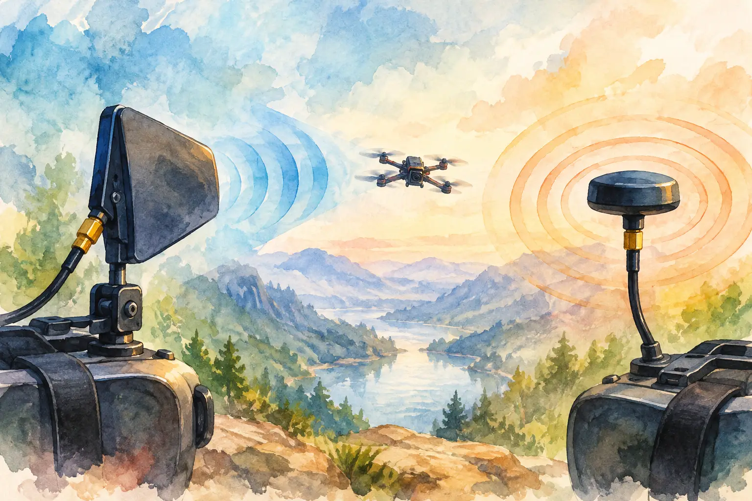
An omni antenna is designed to provide broad coverage around its vertical axis. In practical FPV use, a circularly polarised cloverleaf, lollipop or stubby antenna creates a doughnut-shaped radiation pattern. It gives useful coverage around the pilot without requiring you to point it at the aircraft.
A directional antenna concentrates its receive or transmit energy into a narrower forward-facing area. Patch, panel, helical and crosshair designs are common examples. By focusing energy in one direction, a directional antenna can provide more gain and a stronger usable signal at distance, but only inside its beamwidth.
That trade-off is the entire decision. Omni antennas favour freedom of movement. Directional antennas favour range and penetration in a defined flight sector.
Gain is often expressed in dBi, but it should not be read as free performance. A higher-gain antenna achieves its advantage by reducing coverage elsewhere. If a patch antenna delivers a cleaner picture far ahead of you, it may be markedly weaker to the side, above, below or behind the pilot. The useful question is not “which antenna has more gain?” It is “where must this aircraft maintain a clean link?”
When an omni antenna is the better flight tool
Use an omni antenna when the aircraft can move anywhere around you, particularly at short to medium range. Freestyle flying, tight racing tracks, bando sessions and technical proximity work all reward broad, forgiving coverage. You should be able to concentrate on the gap, power loop or recovery line rather than continually managing the aircraft’s relationship to a beam.
Omnis are also well suited to launch and landing. A directional antenna may have a weak zone close to the pilot or outside its intended elevation angle. An omni keeps coverage more consistent while the aircraft is low, nearby and changing direction quickly.
The compromise is reduced range compared with a properly aimed directional alternative. An omni also cannot eliminate every null. The familiar doughnut pattern is weakest directly above and directly below the antenna, and frame shadowing can make those weak areas worse. Antenna placement still matters. Keep the active element clear of carbon fibre, batteries, flight electronics and other RF hardware where possible.
For an aircraft transmitter, an omni is often the sensible default because the quad can yaw, roll and pitch through the flight. A directional VTX antenna can produce excellent results only when the aircraft’s orientation remains predictable relative to the ground station. That is uncommon in aggressive FPV flying.
When directional antennas earn their place
A directional antenna is the stronger choice when you fly primarily in front of a fixed operating position. Long-range cruising, ridge routes, open-field work and planned inspection-style missions all fit this pattern. When the aircraft remains inside the main beam, extra receive gain can turn a marginal image into a controlled, usable feed.
Directional designs can also help in electrically noisy locations. Their narrower acceptance area may reduce unwanted signals and reflected energy arriving from the sides and rear. This is helpful, but it is not a cure for poor frequency planning, an overloaded receiver or an obstructed flight path.
Beamwidth is as important as gain. A wide patch may offer a practical blend of reach and forgiveness. A high-gain helical can extend performance further, but demands more accurate aiming. If you are standing in one place while flying a defined valley or corridor, that focus is an advantage. If the route spreads across a broad horizon, an overly narrow beam can become the failure point.
Elevation matters too. A directional antenna has a three-dimensional coverage pattern, not a flat cone drawn on a product page. Set the ground station at an appropriate height and angle for the expected flight line. Pointing a high-gain patch at the horizon may leave poor coverage for close, low flying. Aim for the area where the aircraft will spend most of its time, not simply the furthest point on the map.
The strongest FPV setup is often a combination
For most pilots using a diversity receiver, the practical answer is not directional or omni. It is both. Fit an omni antenna to one receiver input and a directional antenna to the other. The receiver can use the stronger feed as the aircraft changes position, giving broad nearby coverage alongside improved forward range.
This arrangement is effective because it accepts how real flights unfold. The omni covers take-off, landing, turns and unexpected recovery lines. The directional antenna supports the intended outward route. Rather than forcing one pattern to do every job, diversity lets each pattern handle the geometry it suits.
Not all diversity systems make switching decisions in exactly the same way, and antenna ports may have specific requirements. Check whether the receiver uses true diversity, rapid switching or another combining method. A poorly configured diversity system can still make the wrong choice at the wrong time.
For fixed-wing FPV, a forward directional antenna at the ground station paired with an omni is especially compelling when flights follow a planned sector. For freestyle quads, dual omnis or an omni with a wide patch may be more useful than a narrow, high-gain antenna. The correct balance depends on the flying envelope, not the aircraft category alone.
Match polarisation before chasing gain
Antenna pattern does not override polarisation. A right-hand circularly polarised antenna should normally be matched with right-hand circular polarisation at the other end of the link. The same applies to left-hand circular polarisation. Mixing RHCP and LHCP creates a major signal loss that extra antenna gain will not recover.
Circular polarisation is widely used in analogue FPV because it handles multipath reflections better than linear systems in many environments. Reflected signals often change polarisation, allowing the intended signal to remain more distinct. That does not mean circular polarisation defeats concrete, metal, wet foliage or terrain. It simply gives the link a better chance in reflection-heavy spaces.
Linear antennas can still be the correct choice where the transmitter and receiver orientation is controlled and the system is designed around linear polarisation. Do not mix types casually. Match the full system: frequency band, connector, impedance, polarisation and intended antenna orientation.
Range is about the entire link budget
An antenna upgrade cannot compensate for every weak point. Video transmitter output, receiver sensitivity, frequency congestion, feedline loss, connector condition, antenna placement and obstacles all influence the final result. A damaged coax lead or loose connector can erase the benefit of a premium directional antenna.
The terrain between aircraft and pilot is often the deciding factor. A clear line of sight is valuable, while even a low ridge, dense trees or a building can attenuate a 5.8 GHz link heavily. The Fresnel zone matters as well. You do not need a physical obstacle directly in the line between antennas to lose performance; objects close to that line can disrupt the signal path.
This is why a high-gain antenna may disappoint in a wooded site but excel in open terrain. It is not necessarily a product fault. RF behaves according to the environment, and the environment changes from one launch point to the next.
A practical selection process
Start with the intended flight shape. If you fly all around yourself, choose an omni-led setup. If most flights travel through a known forward sector, add a directional receiver antenna. If your route is long, narrow and predictable, consider more gain with the discipline to aim it accurately.
Then verify compatibility. Confirm your video band, connector type and polarisation, and avoid adding unnecessary adapters. Every adapter and length of coax introduces loss or another potential mechanical failure point. Mount the antenna where it has the clearest possible view, then inspect the connector before each session.
Finally, test in the environment where you actually fly. Fly controlled passes at different ranges, heights and angles rather than judging a setup from one straight outbound run. Watch for break-up on side approaches, low returns and turns behind obstacles. Those are the moments that reveal whether the pattern supports your real flight vision.
Aviadiag supports builders who need to configure video links around more than standard hardware. Select the antenna pattern as deliberately as you select the VTX, receiver and airframe, and your FPV system will be better prepared for the line you intend to fly.