Have Additional Questions? Contact Us: info(at)aviadiag.com

A clear FPV feed can fail long before your transmitter reaches its quoted power limit. A poorly matched aerial can throw away signal strength, invite reflected interference and turn a clean run into breakup behind the first obstacle. This antenna polarisation guide focuses on the part of the video link that builders can control immediately: matching the transmitting and receiving aerials to the way the aircraft actually flies.
What antenna polarisation means in an FPV build
Polarisation describes the orientation of an antenna’s electromagnetic field. It is not the direction the aerial points, nor simply whether it sits vertically or horizontally on the frame. For FPV video systems, the practical choice is usually between linear polarisation and circular polarisation.
A linear aerial radiates in one plane. A basic dipole, sleeve dipole or patch may be vertically or horizontally polarised depending on its physical orientation. Two linear aerials work best when their planes match. Turn one aerial through 90 degrees relative to the other and the received signal can fall sharply, even when both components are high quality and on the same frequency band.
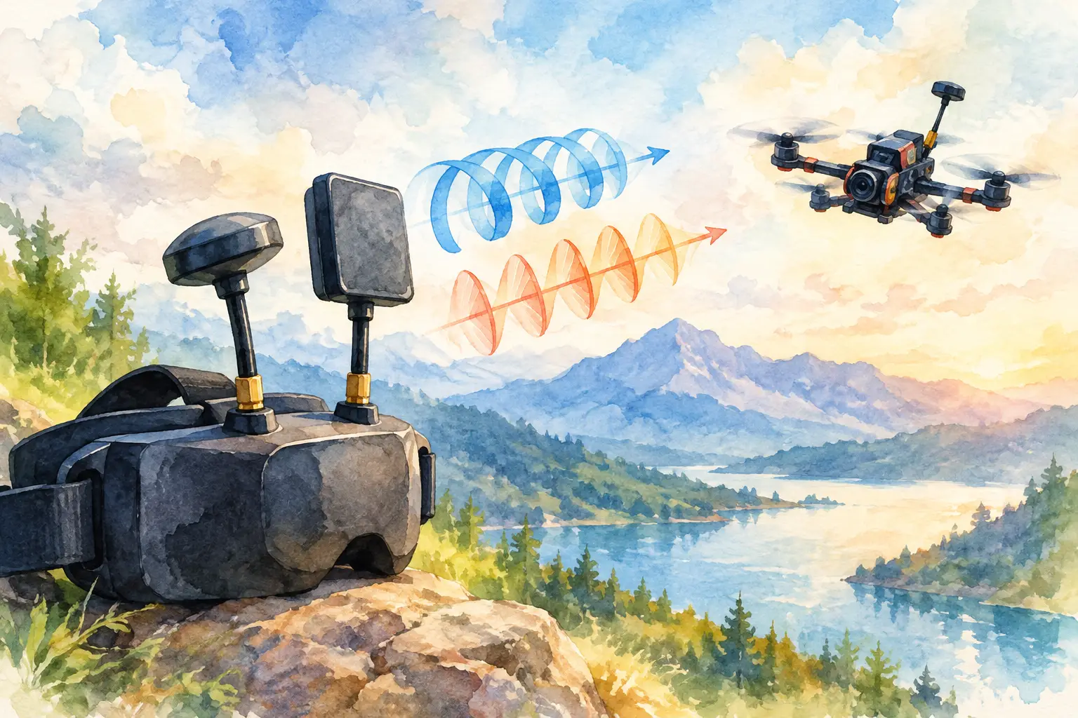
Circularly polarised aerials rotate the field as the signal travels. They come in two senses: right-hand circular polarisation (RHCP) and left-hand circular polarisation (LHCP). An RHCP transmitting aerial is designed to work with an RHCP receiving aerial. LHCP must likewise meet LHCP. Matching the handedness is non-negotiable if link performance matters.
Why circular polarisation suits many FPV video links
An FPV drone does not hold a fixed attitude. It rolls through corners, pitches under throttle and yaws during corrections. A linear aerial on the aircraft changes orientation continually, so its alignment with a linear receiver aerial is never stable. That is manageable for a controlled, level platform, but it creates avoidable variation on an agile FPV build.
Circular polarisation is more tolerant of that rotation. The aircraft can bank and turn without producing the same deep orientation losses associated with crossed linear aerials. This is why circularly polarised omnidirectional aerials are a common choice on analogue FPV transmitters and receiver goggles or ground stations.
Circular polarisation also helps manage multipath. Reflections from buildings, ground, vehicles and metal structures can arrive at the receiver slightly later than the direct signal. Those delayed copies can create fading, ghosting or a sudden loss of usable image. A reflected circular signal often reverses handedness, allowing a correctly polarised receiving aerial to reject part of that reflected energy. It is not a cure for flying behind dense concrete or terrain, but it can make a real difference in cluttered environments.
The trade-off is that circular aerials are more complex, more exposed and more sensitive to damage. Bent lobes, crushed protective covers or poor-quality construction can degrade their axial ratio – a measure of how cleanly the aerial produces circular polarisation. A cheap circular aerial with poor geometry may perform worse than a well-installed linear dipole.
Match the whole signal path
The most expensive receiver aerial cannot recover performance lost at the transmitter. Start by confirming the polarisation on every RF component in the chain: video transmitter aerial, receiver aerial, goggles module aerials and any relay or ground-station hardware.
For a circular system, use RHCP throughout or LHCP throughout. Combining RHCP and LHCP produces strong cross-polarisation rejection. In practice, that means a severe signal penalty rather than a small efficiency loss. The image may appear usable at close range, then collapse much earlier than expected as distance or obstruction increases.
For a linear system, align the transmitting and receiving aerials in the same plane. A vertically mounted drone dipole works best with a vertically oriented receiver dipole or patch designed for that orientation. If the airframe will spend much of its flight banked or inverted, expect the alignment to change. That does not rule out linear polarisation, but it should shape your build decision.
Do not confuse connector gender with polarisation. SMA and RP-SMA describe the connector interface, not RHCP or LHCP. Check both before fitting an aerial. A connector mismatch can damage the centre pin or create an unreliable RF connection; a polarisation mismatch can quietly reduce the range you thought you had built.
Choosing linear or circular aerials
Linear polarisation remains a valid choice when simplicity, size and weight matter. A compact dipole on a small build is light, inexpensive and effective for close-range flying. It is also common in digital systems where the supplied aerials and receiver design are intended to operate as a matched linear setup. Keep the aircraft aerial clear of carbon fibre, battery leads and conductive hardware, then maintain sensible receiver alignment.
Circular polarisation is usually the stronger option for freestyle, variable-attitude flying and analogue setups exposed to reflections. A typical arrangement is an omnidirectional circular aerial on the aircraft, paired with an omnidirectional aerial and a directional aerial at the receiver. The omni maintains coverage around the pilot, while the directional aerial concentrates gain where the aircraft is expected to fly.
The correct choice still depends on the mission. A long-range route flown mainly in one known direction may benefit from a directional receiver aerial, but that aerial has a narrower coverage area. Fly outside its beam and the gain advantage disappears. A compact cinewhoop working indoors may value multipath handling, yet its aerial must survive prop wash and tight gaps. There is no universal best aerial – there is only the best match for the airframe, environment and intended flight line.
Omnidirectional versus directional is a separate decision
Polarisation and radiation pattern solve different problems. An omnidirectional aerial aims to cover a broad area around itself, while a directional aerial focuses energy in a particular direction. Either can be linear or circularly polarised.
On the aircraft, omnidirectional coverage is normally preferred because the drone moves in every direction relative to the pilot. At the receiving end, a directional patch or helical aerial can extend useful range and improve rejection of interference outside its beam. Pairing it with a compatible omni receiver aerial gives diversity systems a practical choice as the aircraft changes position.
Installation mistakes that cost video-link performance
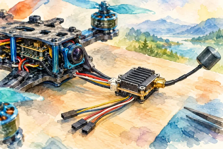
Aerial placement matters as much as the label on the packet. Carbon fibre is conductive and can block, reflect or detune RF energy. Mount the transmitting aerial so its active element sits clear of the frame, electronics stack, battery and high-current wiring. On a circular aerial, keep the radiating section fully outside the carbon structure rather than leaving it pressed against a plate or trapped under a strap.
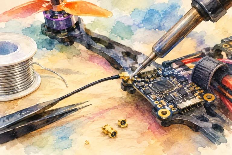
Avoid placing the aerial directly in prop wash if vibration can flex the coaxial lead or strike the aerial against the frame. A flexible mount can protect the connector in a crash, but it must still hold the aerial consistently in clean air. Inspect the coax after impacts. A damaged inner conductor, loose connector or stressed solder joint may look harmless while adding enough loss to compromise the link.
At the receiver, separate aerials where practical. Two aerials pressed together do not provide meaningful spatial diversity. Keep them oriented and positioned to give the receiver different views of the signal path. If one aerial is directional, aim it at the main flight area rather than at the take-off spot by habit.
Before a serious flight, check four things: the aerial is fitted before powering the video transmitter, connector types are correct, circular handedness matches, and no aerial is hidden behind conductive material. That short routine prevents many faults mistakenly blamed on transmitter power or receiver quality.
A field test that reveals polarisation problems
Do not judge a new aerial setup only from a bench test at arm’s length. Power the complete aircraft in a safe, legal test area and walk or fly through the positions that normally expose the link: behind a tree line, around a structure, at the edge of the intended flight zone and through moderate bank angles. Watch for repeatable breakup rather than a single random glitch.
If performance is weak, change one variable at a time. Confirm handedness first, then inspect aerial condition and placement, then test receiver orientation. Swapping everything at once can hide the real fault. Keep known-good aerials in your field kit so you can isolate whether the problem is the transmitter, receiver, coaxial lead or the aerial itself.
For specialised FPV video builds, Aviadiag can help source components around the required transmitter, receiver and flight objective. Start with the signal path, not the advertised gain figure. A matched, well-mounted aerial pair usually delivers more usable video than a powerful system with poor polarisation discipline.
The next time your feed breaks up in a turn, look at aerial geometry before reaching for more milliwatts. Matching polarisation and placing the aerials deliberately gives your video link the margin to keep working when the flight becomes demanding.