Have Additional Questions? Contact Us: info(at)aviadiag.com


A video feed that breaks up behind a tree line is rarely fixed by blindly selecting the highest setting. FPV transmitter power output explained starts with a simple fact: milliwatts affect only one part of the video link. Antenna quality, receiver sensitivity, frequency congestion, installation, terrain and legal operating limits can matter just as much.
For a purpose-built FPV aircraft, transmitter power should be chosen to support the flight profile, not to compensate for a weak overall setup. The right output gives you usable image quality at the range and penetration your build demands, while keeping heat, battery draw and interference under control.
What FPV transmitter power output actually means
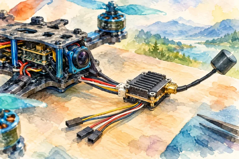
Video transmitter, or VTX, power is usually stated in milliwatts (mW). It describes how much RF power the VTX sends to its antenna port. Typical analogue VTX settings might include 25 mW, 100 mW, 200 mW, 400 mW, 800 mW and 1 W or more. Digital systems use their own permitted settings and link-management behaviour, but the same principle applies: higher output can strengthen the transmitted signal at the receiver.
The relationship is not linear in flight. A 400 mW setting does not produce four times the practical range of 100 mW. Radio propagation follows a logarithmic scale and is heavily affected by obstructions, antenna orientation and noise. Doubling power offers a modest gain, not a dramatic transformation.
That is why dBm is useful when comparing hardware. Every increase of 3 dB approximately doubles power. 25 mW is about 14 dBm, 100 mW is 20 dBm, 400 mW is 26 dBm and 1 W is 30 dBm. Moving from 25 mW to 400 mW is a major increase in transmitted power, yet it will not overcome a badly positioned receiver antenna or a carbon frame blocking the VTX antenna.
FPV transmitter power output explained for real flights
For close-range flying in open space, low power is often the better engineering choice. It reduces heat, consumes less from the flight battery and lowers the chance of disturbing other pilots on nearby channels. A clean 25 mW or 100 mW setup with correctly polarised antennas can produce an excellent image for local circuits and organised flying sites.
As distance increases, or when the aircraft must work around light foliage, buildings or terrain, stepping up power provides additional link margin. That margin is valuable because it gives the receiver more signal above the noise floor as conditions change. It should be treated as a reserve, not as permission to fly beyond a safe recovery margin.
High power becomes more relevant for specialised builds that need a resilient analogue link across challenging terrain, provided the installation, antennas and operating authority support it. A long-range aircraft equipped with a directional ground-station antenna can often achieve more from a carefully aligned receive system than from a dramatic VTX power increase alone.
The operational objective should drive the setting. A compact freestyle quad, a cruising platform and a custom aircraft with a fibre-based control or video architecture do not carry the same heat budget, battery capacity or signal-link requirement. Tailor the video system to the mission rather than fitting the biggest available number.
More milliwatts bring real trade-offs
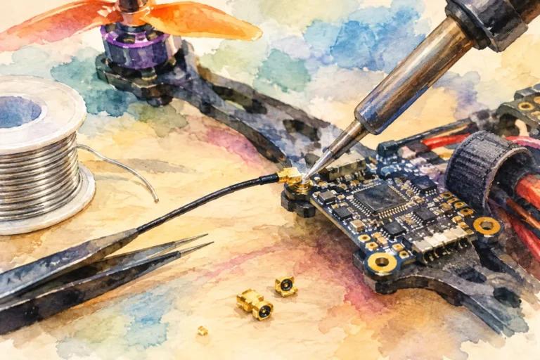
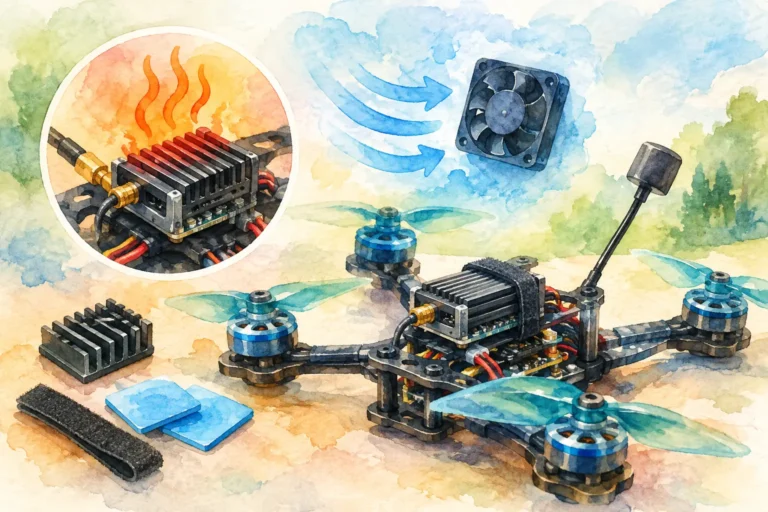
Power output creates heat. On the bench, a VTX running at 800 mW or 1 W can become hot enough to damage itself if there is no airflow. A fan is sensible during configuration, particularly when checking channels, camera feed and OSD before fitting the aircraft canopy. Never power a VTX without an antenna connected, as reflected energy can damage the transmitter.
In flight, propwash may provide enough cooling, but enclosed frames and tightly packed electronics still deserve attention. Place the VTX where it has a reasonable airflow path, keep it away from heat-sensitive wiring where possible, and confirm that its rated input voltage matches the build. A higher-power transmitter may also create more electrical noise, especially in poorly filtered installations.
Battery draw is another consideration. The VTX is not normally the largest load on a multirotor, but high output can be significant on small packs, endurance aircraft or systems with several support electronics. Powering the VTX from a clean, regulated supply helps avoid video noise caused by voltage sag and electrical interference.
There is also an RF trade-off. Excessive output can desensitise nearby receivers and make shared-frequency flying harder. At a flying field, one pilot operating at high power on an adjacent channel may degrade another pilot’s image even when both channels appear separated. Good frequency planning and sensible power settings are part of safe group operation.
Antennas can deliver the gain power cannot
Before increasing VTX output, inspect the antenna system. A quality circularly polarised antenna matched to the receiver is normally more valuable than an arbitrary power increase. Right-hand circular polarisation should be paired with right-hand circular polarisation, and left-hand with left-hand. Mixing them creates a major signal loss.
Antenna placement matters as much as the model. Keep the radiating element clear of carbon fibre, metal hardware and high-current wiring. Carbon fibre can obstruct or distort RF energy, so an antenna trapped against a frame plate will not perform like the same antenna mounted clear of the aircraft.
On the ground side, diversity receivers and a combination of omni and directional antennas can materially improve usable coverage. An omni antenna supports broad awareness around the pilot. A patch or other directional antenna concentrates reception in the intended flight area. The receiving system determines what reaches the goggles or monitor, so it deserves the same attention as the VTX.
Choosing a practical power setting
Begin at the lowest setting that suits the planned flight. Test the image in the actual environment, not only on a workbench or in an empty field. Fly predictable passes at conservative distance, monitor picture quality, and check how the link reacts when the aircraft turns, drops behind foliage or changes altitude.
If the image loses stability, first verify the channel, antenna connectors, antenna polarisation and VTX mounting. Then assess whether the receiver position provides a clear view of the flight area. Only after those fundamentals are correct should output power be increased.
A useful starting point is 25 mW to 100 mW for close-range operation, 200 mW to 400 mW where a stronger margin is genuinely needed, and higher settings only where the aircraft, cooling, receiving setup and legal conditions justify them. These are setup principles rather than universal rules. A clean 200 mW system can outperform a poorly configured 1 W system by a wide margin.
Digital VTX systems require the same discipline, even when their image remains sharp until the link reaches a threshold. Their advertised power level is one variable among several, including bitrate mode, antenna system, receiver placement and firmware configuration. Treat any claimed range as conditional on the complete RF environment.
Know the legal and site limits
Transmitter power, frequencies and equipment approvals are regulated. In Great Britain, permissions and permitted technical parameters depend on the radio equipment, frequency band and how it is operated. Organised clubs or sites may also set stricter requirements to protect shared airspace and prevent interference.
Check the applicable rules before selecting a high-power mode, and follow any site frequency-control process. Keep the aircraft within the required operating framework and maintain a reliable method of control and recovery. A stronger video link is not a substitute for disciplined flight planning.
For builders sourcing specialised FPV transmitters, receivers or optical-fibre hardware, the right question is not simply, “What is the highest output available?” Ask what output supports the aircraft’s intended distance, environment, cooling capacity and receive setup. Build the whole link with that answer in mind, then use power as the final margin that helps your aircraft fly with confidence.