Have Additional Questions? Contact Us: info(at)aviadiag.com

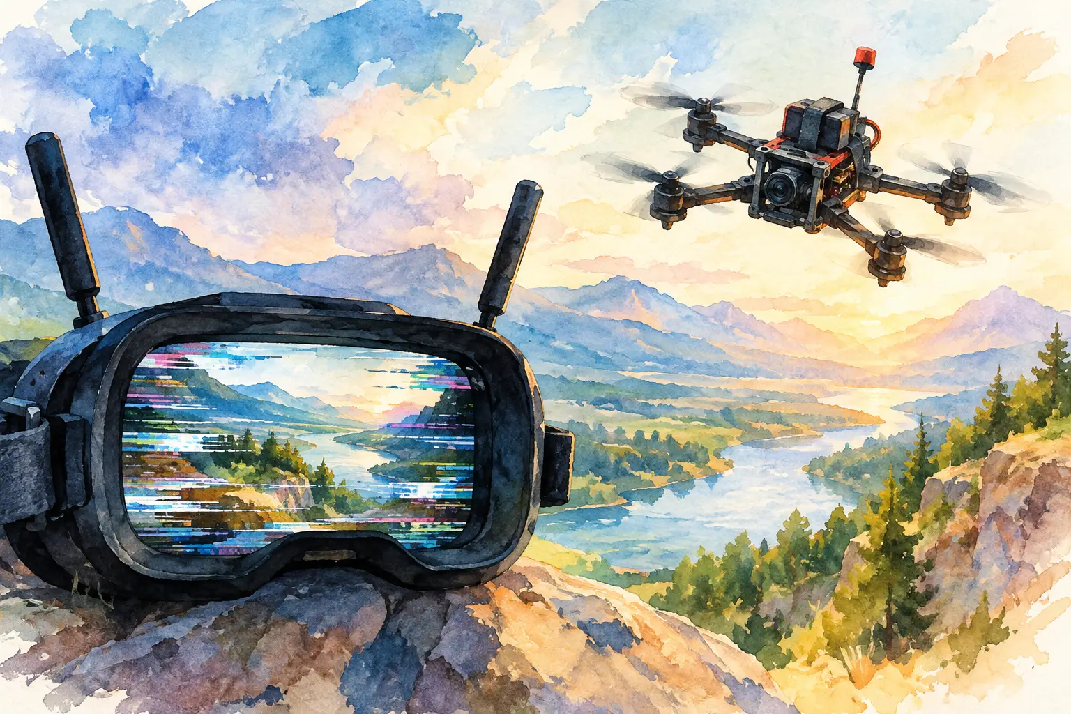
A flickering FPV feed is not a minor visual annoyance when the aircraft is moving fast, low or beyond easy line of sight. Understanding why video flickers lets you isolate the failure point before replacing parts at random. In most builds, the cause sits in one of four places: the power path, the RF link, the camera and video wiring, or the goggles and receiver configuration.
Read the Flicker Before You Change Anything
The pattern matters. A rapid horizontal roll or moving bars often points to electrical noise entering an analogue video system. Brief black-outs, colour shifts or a feed that returns after a split second can indicate a loose connector, voltage drop, overheating transmitter or camera fault.
Static that grows as distance increases is usually an RF problem rather than a power issue. If the picture stays clear on the bench but breaks up as soon as the motors spool up, start with the power system and wiring layout. If it degrades only when the aircraft changes direction, antenna orientation, airframe shadowing or multipath reflection is more likely.
Digital FPV systems can appear to flicker differently. Instead of traditional snow, you may see frozen frames, block artefacts, sudden quality reduction or a momentary grey screen. The source can still be poor power, heat or weak RF conditions, but the display behaviour is determined by the digital link’s error correction and bitrate management.
Why Video Flickers When Motors Are Running
Motors, ESCs and switching voltage regulators produce electrical noise. A well-built FPV power system controls that noise before it reaches the camera and video transmitter. A compromised system lets it ride directly into the video signal.
On an analogue build, a damaged or undersized capacitor at the battery input is a common source of throttle-linked lines in the image. Fit the capacitor close to the main battery pads, observe polarity, and use a voltage rating with proper headroom for the battery configuration. A capacitor can look intact while performing poorly, particularly after a hard impact or repeated high-current use.
The VTX and camera also need stable supply voltage. Supplying either component from an overloaded BEC, an incorrect voltage pad or a noisy rail can create flicker even with a clean main battery connection. Check the component specifications rather than assuming every 5 V, 9 V or battery-voltage output is interchangeable. A VTX that accepts a wide input range may still behave better on a regulated supply if the build is electrically noisy.
Ground routing deserves the same attention. A loose ground, a partially broken camera lead or a poor solder joint creates resistance and instability. Inspect joints under magnification, then gently move the harness while the system is powered with props removed. If the image changes, cuts out or develops noise, repair that connection before investigating more complex causes.
Keep camera and video leads away from battery cables, ESC power leads and motor phase wires where practical. Crossing is usually preferable to running them in parallel for a long distance. On tight frames, physical separation is limited, so clean soldering, a suitable capacitor and a filtered power rail become more important.
RF Problems That Look Like Video Failure
A strong transmitter cannot overcome a badly matched or damaged antenna system. When the RF link is the problem, the feed often looks normal nearby and worsens with range, behind obstacles or during turns. This is where operators can mistake expected link limitation for a defective VTX.
Confirm that the transmitter and receiver are on the same band and channel, then inspect every antenna connector. A partly seated MMCX or u.FL connector, a pinched coax lead or a cracked antenna element can reduce effective range dramatically. Never power a VTX without the correct antenna attached. The reflected energy can damage the transmitter output stage and create a fault that is difficult to diagnose later.
Polarisation must also match. A right-hand circularly polarised antenna paired with a left-hand circularly polarised antenna will lose a significant amount of signal. Linear antennas can work, but they are generally more vulnerable to changes in aircraft orientation and reflections from buildings, ground and metal structures.
Receiver placement matters on larger platforms. Carbon fibre, batteries, flight controllers and other electronics can shadow antennas or create unwanted coupling. Position antennas clear of conductive material where possible and preserve their intended geometry. For directional receiving setups, remember the trade-off: higher-gain antennas extend performance in the direction they face but narrow the useful coverage area.
Optical-fibre video architectures change the RF equation, but they are not immune to interruption. Tight bends, contaminated connector faces, damaged fibre and poor strain relief can cause intermittent optical performance. Treat the fibre path as a precision connection, not as ordinary wire.
Camera, VTX and Display Mismatches
Not every flickering image originates in the airframe. Analogue cameras may be set to PAL while goggles, a DVR or an external display expects NTSC, or the reverse. Some equipment detects the format automatically; others do not do it reliably. A format mismatch can produce rolling, unstable or cropped video.
Check the camera menu settings, VTX input configuration and receiver or display options as a complete chain. Also verify aspect ratio. A 4:3 camera connected to a 16:9 display should not normally cause electrical flicker, but an incorrect scaling setting can make a healthy feed look wrong enough to send troubleshooting in the wrong direction.
Heat is another overlooked factor. A VTX may work perfectly on the bench for a short period, then flicker or reduce output after temperature rises. Bench testing without prop wash is particularly harsh. Make sure the transmitter has sufficient airflow in flight, is not trapped against heat-retaining material, and is configured for the output power you genuinely need. More power can improve a difficult link, but it also creates more heat and draws more current.
A Fast Isolation Process for FPV Video Flicker
Start with a props-off bench test using a known-good battery. Watch the feed with motors disarmed, then check it again while motors are armed at low throttle only when the aircraft is safely restrained and your operating procedures allow it. A change that follows throttle strongly suggests power noise, grounding or ESC-related interference.
Next, substitute one known-good item at a time. Test a different camera, camera lead, VTX antenna, receiver antenna or pair of goggles where available. Do not change several parts together. A clean result after five changes tells you little about which component actually caused the issue.
Then reduce the system to the shortest dependable path: camera to VTX, VTX to receiver, receiver to display. Remove an OSD board, external recorder, adaptor or extension cable temporarily if it sits in the video chain. Once the image is stable, add components back one at a time.
Finally, test at realistic temperature and distance. A link that holds for thirty seconds on a workbench has not proven itself in flight. Monitor VTX temperature, battery voltage behaviour and receiver performance across the manoeuvres your mission or build is intended to handle.
Build the Video Link Around the Flight Requirement
The right repair depends on the intended aircraft. A compact freestyle build may prioritise low mass, protected wiring and adequate cooling. A long-range platform needs greater attention to antenna placement, receiver diversity, component reliability and predictable power delivery. A specialised tethered or fibre-based configuration has its own requirements for connector protection and cable management.
Choose FPV transmitters, receivers, antenna hardware and optical-fibre components as a matched system, not as isolated upgrades. Aviadiag supports builders who need component-level options for standard repairs and specialised video-link configurations.
When a feed flickers, resist the urge to turn up transmit power first. Find the exact point where image stability is lost, correct that weakness, and your aircraft will carry a video link that supports the way you intend to fly.