Have Additional Questions? Contact Us: info(at)aviadiag.com

A build can look complete on the bench and still fail at the first arm because one connector, voltage rail or signal protocol was assumed rather than checked. This drone component compatibility guide is built for FPV pilots and custom builders who want every part to serve a defined flight objective, from a clean analogue video feed to a purpose-built optical-fibre configuration.
Compatibility is not a single specification. A video transmitter may power up correctly yet be unsuitable for the receiver, antenna polarisation or operating environment. A flight controller may physically accept a plug while lacking the UART capacity, firmware support or voltage tolerance the peripheral requires. Build around verified interfaces, not product labels.
Drone component compatibility guide: start with the system
Before choosing a component, define the aircraft’s role and its operating constraints. A compact freestyle quad, long-range platform and specialised tethered or fibre-linked aircraft need different compromises in weight, power reserve, thermal management and signal architecture. The right part is the part that supports the whole system without forcing unreliable workarounds.
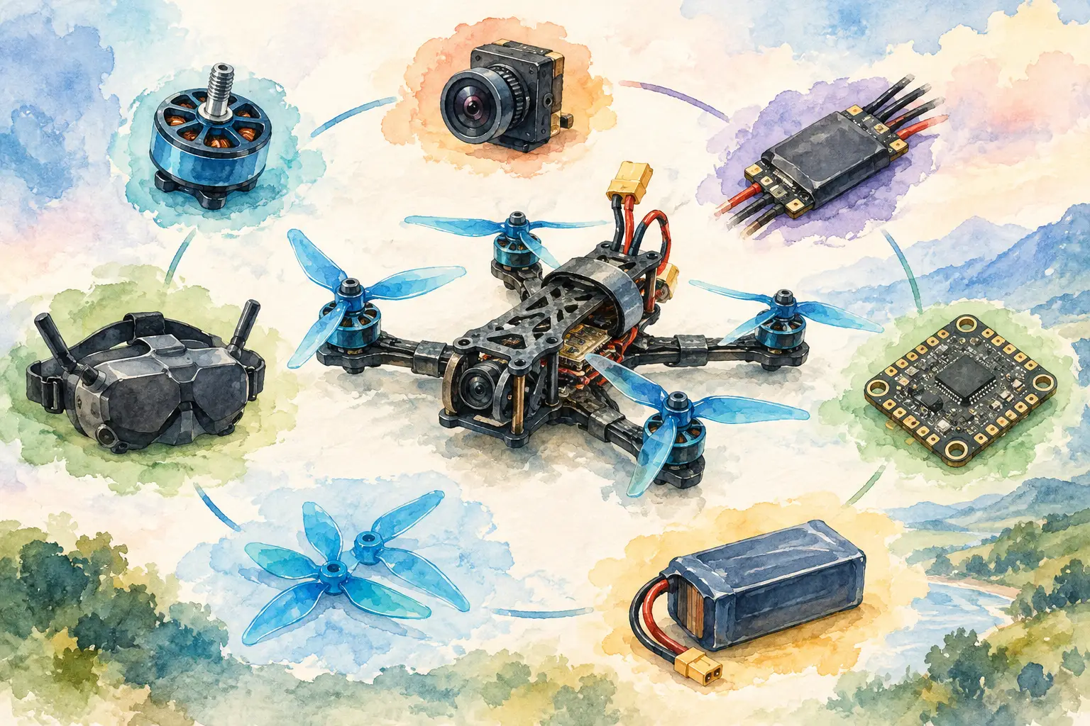
Map the build in four layers: flight control, power distribution, video link and command or telemetry. Then identify the connection between each layer. Record voltage, current demand, connector type, data protocol, physical mounting space and firmware requirements. This takes minutes early in the build and can prevent a costly chain of replacements later.
Do not treat advertised compatibility as universal compatibility. A component described as suitable for FPV may support only a particular video format, connector family or supply range. Product descriptions are a starting point; pinout diagrams and electrical specifications are the decision point.
Match power before signal
Voltage mismatch is one of the quickest ways to damage otherwise capable hardware. Check the battery cell count, ESC input rating, flight controller regulator output and the acceptable input range for every accessory. Video transmitters, receivers, cameras, GPS units and fibre-related hardware may all have different power needs.
The key distinction is between input voltage and regulated output voltage. A flight controller might accept a 4S or 6S battery directly, while its 5V pad has a limited current budget. Connecting a high-draw transmitter to that pad can cause brownouts, noise in the image or regulator failure even when the stated voltage is correct.
Calculate current with real operating conditions in mind. A bench test at low transmitter power does not represent a warm aircraft running at a higher output level. Leave headroom for peak load, particularly where a video transmitter, digital air unit or additional link hardware shares a regulated supply.
Use a common ground wherever components exchange analogue signals or serial data. Without it, video can roll or break up, telemetry can become unreliable and control inputs may behave unpredictably. Keep power wiring short and appropriately rated, but do not simply use heavier cable everywhere. Added mass affects handling, flight time and the space available for cooling.
Build the video link as a matched chain
An FPV video system is only as capable as its weakest link. Confirm whether the camera, transmitter, receiver and display equipment use the same video standard. Analogue and digital systems are not interchangeable by default, and even within analogue equipment, supported bands, channels and audio functions can vary.
For analogue builds, verify camera output format, transmitter channel coverage and receiver support. PAL and NTSC compatibility is often manageable, but not every display or recorder handles both equally well. Check the camera connector and pinout too. JST-style plugs can look identical while carrying power, ground, video and control wires in a different order.
Antenna selection needs the same discipline. Match the connector type at the transmitter and receiver, such as SMA or RP-SMA, and avoid relying on visual similarity. They are mechanically close but electrically different. Match polarisation as well: a right-hand circularly polarised transmitting antenna should normally pair with a right-hand circularly polarised receiving antenna. Combining opposite polarisation can severely reduce usable signal strength.
Gain, antenna pattern and placement are trade-offs rather than upgrades in isolation. A high-gain directional receiving antenna can extend reach in its intended direction, but it demands better aiming and offers less coverage around the pilot. On the aircraft, place antennas clear of carbon fibre, battery leads and high-current wiring where possible. Carbon frames and poor antenna placement can obstruct or distort the signal even when every item is nominally compatible.
Check control, telemetry and flight-controller ports
Flight controllers are connection hubs, not unlimited expansion boards. Count available UARTs before committing to an ELRS receiver, GPS, telemetry radio, video-transmitter control protocol and other serial peripherals. Two devices cannot share one UART unless the specific hardware and firmware arrangement supports it.
Confirm the protocol at both ends. Receiver support for CRSF, SBUS or another control protocol must align with the flight controller configuration. Likewise, a video transmitter’s control interface may depend on SmartAudio, Tramp or a dedicated digital connection. Correct wires attached to the wrong serial settings will produce a system that appears wired properly but cannot communicate.
Firmware is part of compatibility. Check that the flight-controller target supports the processor board, that the configurator version recognises it and that the desired receiver or transmitter features are available in the installed release. Update only with a recovery plan, saved configuration and an understanding of target selection. Firmware can expand capability, but it cannot override electrical limits or missing hardware ports.
Plan physical fit, cooling and vibration control
Dimensions are not cosmetic details. Confirm mounting-hole patterns, stack height, cable exit direction and clearance for capacitors, USB access and antenna routing. A 20 x 20 mm stack and a 30.5 x 30.5 mm stack may both fit within a frame visually, yet need different hardware and leave very different room for wiring.
Heat is another compatibility factor. Video transmitters and high-output electronics need airflow and should not be enclosed against foam, heat-shrink or tightly packed wiring. Conversely, exposed components need protection from prop strikes, moisture and debris. Choose mounting positions that balance cooling, service access and crash resistance.
Use soft mounting where vibration-sensitive hardware benefits from it, but avoid letting a board move enough to strain solder joints or contact conductive carbon. Secure every antenna lead and fibre run so that normal vibration cannot pull on a connector. A clean installation is easier to diagnose and more likely to hold its performance over repeated flights.
Optical fibre setups demand interface discipline
Optical fibre discs and associated connectivity hardware introduce their own compatibility checks. Start by confirming the fibre type, connector standard, supported link hardware and the intended physical routing. Fibre is not a substitute for arbitrary RF or video hardware; the transmitter, receiver and conversion equipment must be designed to operate as one signal path.
Respect bend radius, spool direction and strain relief. A fibre disc that is electrically appropriate can still suffer attenuation or physical damage if it is sharply bent, crushed or routed through an unprotected edge. Consider the aircraft’s movement, payload placement and recovery process before deciding where the disc sits.
Weight distribution matters here. A fibre disc changes the centre of gravity as material deploys, so flight-controller tuning and mounting location may need adjustment. Test the complete installation progressively in a controlled area rather than assuming bench results will reflect airframe dynamics.
A pre-power compatibility check
Before connecting a flight battery, inspect the build against the specifications rather than memory. The most useful final checks cover four areas:
- Verify every positive, ground and signal wire against the relevant pinout.
- Confirm battery voltage and regulated outputs are within each component’s stated range.
- Check antenna and fibre connections are fitted before powering applicable transmission hardware.
- Use a smoke stopper or current-limited supply for the first power-up, then verify video, receiver input, motor direction and failsafe behaviour without propellers.
This process is not overcautious. It isolates faults while they are inexpensive, protects components during first power-up and gives you a reliable baseline before tuning or field testing.
When a custom requirement changes the answer
Some builds cannot be resolved from a standard compatibility table. A nonstandard airframe, specialised video-link requirement, unusual fibre length or interceptor-oriented configuration may need component selection around dimensions, thermal limits and operating intent that ordinary FPV bundles do not address. In those cases, specify the complete system requirement rather than asking whether a single part will fit.
Aviadiag supports builders sourcing specialised FPV transmitters, receivers, optical fibre discs and tailored hardware configurations. Provide the battery voltage, flight controller model, video format, connector type, mounting space and objective for the build. That information turns a vague compatibility question into a component plan that can be tested with confidence.
The strongest builds are not assembled from the most expensive individual parts. They are built from components that agree on power, signal, fit and purpose. Start with the interfaces, test each stage without propellers, and let the aircraft’s mission decide every upgrade that follows.