Have Additional Questions? Contact Us: info(at)aviadiag.com

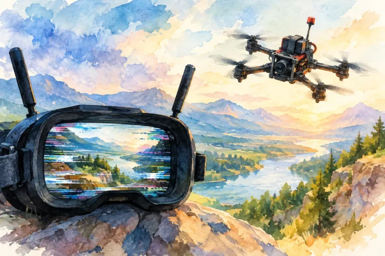
A clean bench image can turn into rolling bars, diagonal interference or a pulsing horizon the moment the motors arm. To troubleshoot FPV ground loops properly, treat the fault as a wiring-path problem first, not automatically as a failed camera, VTX or flight controller. Your video system is showing you where electrical noise is finding a route it should not have.
Ground-loop symptoms are common on analogue FPV builds, particularly where high-current ESC noise, multiple ground returns and add-on devices share a compact frame. Digital systems can suffer from poor grounding and dirty power too, although the failure may present as resets, reduced range or video drop-outs rather than classic horizontal lines. The objective is the same: give every component a controlled power and ground reference, then prove each part of the path under load.
What an FPV Ground Loop Actually Looks Like
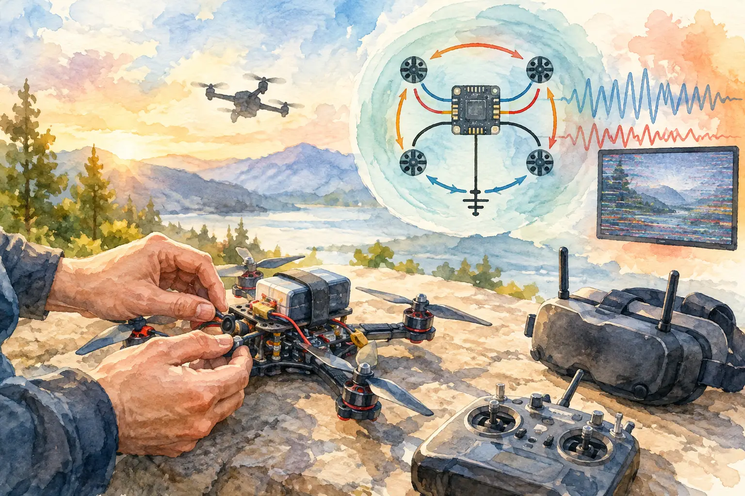
A ground loop occurs when connected components have more than one effective route back to ground. Those routes can sit at slightly different electrical potentials as motor current changes. Your camera and video transmitter then see that variation as unwanted signal mixed into the video feed.
The usual sign is interference that changes with throttle. It may be faint at idle and intensify sharply during a punch-out. Horizontal bands that crawl slowly can also point to a power issue, but not every noisy picture is a true ground loop. A failing regulator, noisy ESC supply, damaged camera lead, poor antenna connection or VTX overheating can create similar symptoms.
That distinction matters. Adding filters at random can hide the cause while adding weight, complexity and another potential failure point. A stronger build comes from isolating the fault before selecting the component that fixes it.
Troubleshoot FPV Ground Loops in the Right Order
Start with the props removed and use a known-good battery. Inspect the build before changing anything. Look for crushed camera cables, exposed conductors, weak solder joints, bridged pads and ground wires that were omitted because the video signal appeared to work on the bench. Check that the camera, VTX and flight controller are not touching conductive carbon fibre through damaged heat-shrink or mounting hardware.
Then use the simplest diagnostic sequence: test at idle, raise throttle gradually while restrained, and observe whether the noise follows motor speed. If it does, the ESC and battery power path deserve attention. If the image is noisy with motors stopped, look first at the camera supply, VTX supply, video wire routing and the video receiver side.
Do not diagnose through DVR footage alone. Watch the live feed using a receiver and antenna combination you trust. A weak or multipathed RF link can look like onboard electrical noise, especially indoors. Test at short range with a clear line of sight before rebuilding the aircraft around the wrong diagnosis.
Build a single, deliberate video ground path
For a conventional analogue layout, the camera ground, VTX ground and flight controller ground should be connected according to the wiring requirements of the equipment, with short, secure returns. In many builds, camera and VTX grounds both return to the flight controller or to a clean regulated supply point. The correct arrangement depends on whether your flight controller handles the video signal path and whether the camera and VTX share the same regulated rail.
Avoid running a separate, long ground lead from one video component directly to the battery negative while another returns through the flight controller. That can create the second return path that causes trouble. Equally, do not remove a required ground wire in an attempt to break a loop. Video equipment needs a stable reference. The solution is controlled grounding, not incomplete grounding.
Use the wiring diagram for your specific camera, FC and VTX. Some units have dedicated video ground pads, smart-audio or control grounds, and separate power grounds. A wiring arrangement that works on one stack can be wrong on another.
Separate clean power from motor power
Motor and ESC wiring carries fast, high-current switching noise. Keep camera and VTX leads away from battery leads, motor phase wires and ESC signal bundles where practical. Crossing at a right angle is usually preferable to running sensitive video wiring alongside a noisy power lead for the length of the frame.
If your FC provides a regulated 5 V, 9 V or 10 V output rated for the camera and VTX load, it is often the cleanest place to power the video system. Confirm the voltage and current capability before connecting anything. A VTX that demands more current than the regulator can provide may brown out, overheat the regulator or inject its own instability into the rail.
Where the FC rail is not suitable, use a quality external BEC or filtered supply selected for the actual input range and load. A low-ESR capacitor across the main battery pads can reduce ESC-induced spikes and is good practice on many builds, but it will not correct a badly planned video ground path by itself.
Isolate one component at a time
If the interference persists, substitute known-good parts methodically. Power the camera from a separate clean regulated source while retaining the normal video connection. If the picture clears, the original camera supply is contaminated. Next, test the VTX power supply in the same way. Then swap the camera lead, as small signal wires often fail internally after a crash or repeated canopy removal.
Disconnect non-essential add-ons during testing. GPS modules, LEDs, buzzers, action-camera power boards and telemetry devices can introduce noise or create an unintended shared ground route. Reconnect each item individually and repeat the throttle test. This takes longer than fitting a filter first, but it tells you which component needs attention.
Pay particular attention to USB-connected equipment. A ground loop can appear only when the quad is connected to a computer, bench supply, HDMI display or external configuration device. Disconnect USB before flight testing. If the image cleans up immediately, the external device is completing an unwanted ground path.
When Filters Help – and When They Do Not
An LC filter can be effective when the problem is conducted power noise on an otherwise correctly wired analogue system. It should sit in the supply feeding the sensitive equipment, with the current rating matched to the camera and VTX. It is not a substitute for a failed regulator, a poor solder joint or incorrect ground returns.
A dedicated filtered BEC may be the better option where your VTX needs a voltage the FC cannot safely provide. It adds another part to the aircraft, so mount it securely, protect it from prop wash and inspect it after hard impacts. Every extra connection is a trade-off between cleaner power and additional failure points.
Ferrite rings can reduce radiated interference in certain cable layouts, particularly on longer leads, but they are rarely the first answer on a compact FPV quad. Fix routing and power distribution before adding suppression hardware.
Verify the Repair Under Real Load
Once the image is clean on the bench, repeat the test with motors armed and then during a short, controlled hover. Watch for noise at mid-throttle and on rapid throttle changes, not only at full power. A problem that appears only during aggressive current draw can still compromise a precision gap, long-range run or low-light flight where video clarity matters most.
Check VTX temperature as well. A transmitter that is running hot because of poor airflow, excessive output power or an incorrect antenna setup may degrade independently of any ground issue. Never power a VTX without the correct antenna connected.
For new builds, take a photo of the final wiring layout and note the regulated rails used for the camera and VTX. That record makes future repairs faster when you change a receiver, add a GPS module or move to a different video transmitter. Aviadiag supplies specialised FPV components for builders who need to match video-link hardware to a defined aircraft configuration.
A quiet image is not merely cosmetic. It gives you cleaner judgement at speed, stronger confidence around obstacles and a video link that supports the flight you planned. Build the power path with the same care as the propulsion system, and your FPV feed will hold up when the throttle does.