Have Additional Questions? Contact Us: info(at)aviadiag.com

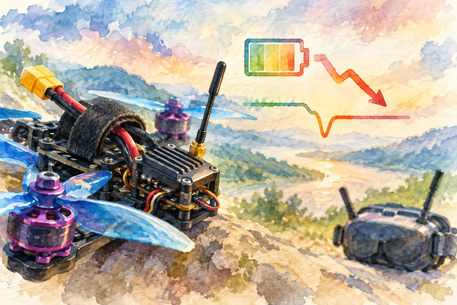
A clean bench test can hide a weak FPV power system. The VTX powers up, the image looks sharp, and then the moment you punch out, the feed flickers, rolls, loses colour, or shuts down completely. Understanding what causes VTX voltage drops means looking beyond the video transmitter itself and tracing the full path from battery to regulator, wiring, connector and ground.
A VTX is only as stable as the supply feeding it. High-output transmitters, digital video units and compact freestyle builds can all expose weaknesses that a lower-power analogue setup may tolerate. The goal is not simply to stop a brownout. It is to build a video link that stays dependable when the aircraft is drawing its highest current.
What causes VTX voltage drops under throttle?
The most common cause is battery voltage sag. When motors demand a large current burst, especially during a punch-out or recovery manoeuvre, the pack voltage falls temporarily. Every battery has internal resistance, and that resistance becomes more noticeable with an ageing pack, a low C-rating, cold conditions, a small-capacity battery, or a build that asks more current than the pack can supply efficiently.
A VTX connected directly to VBAT sees that sag. If its input voltage falls below its operating range, it may reboot, reduce output, or produce unstable video. A flight controller may remain powered long enough to keep the quad flying, while the VTX momentarily drops out. That can make the fault look like an RF issue when it is actually a power issue.
The effect depends on the VTX input specification. A unit rated for a wide direct-battery range may handle a 4S or 6S pack well, but it still has a minimum voltage. A transmitter powered from a regulated 5V, 9V or 10V rail has a different limit: the regulator must maintain its output while the input battery voltage sags and the rest of the aircraft is under load.
Resistance in the power path
Voltage loss is not only created by the battery. It also occurs across every connection between the battery and the VTX. Long, thin supply leads, marginal solder joints, damaged plugs, oxidised connectors and undersized traces all add resistance. Under low current, the loss may be invisible. Under throttle, current rises and the voltage lost across that resistance rises with it.
This is why a VTX can appear healthy on the workbench but fail in flight. The bench supply may deliver stable voltage with little electrical noise, while the aircraft introduces motor current spikes, vibration and real connector loading.
Check the battery lead, XT connector, power distribution path and VTX power pads first. A dull or cracked solder joint can create intermittent resistance that changes with vibration. Also inspect any small plug carrying VTX power. These harnesses are convenient, but their wire gauge and crimp quality still matter when supplying a higher-power unit.
A weak or overloaded voltage regulator
Many FPV builds power the VTX from a regulated rail on the flight controller. This can be the right configuration, provided the regulator is designed for the load. The problem starts when builders assume every labelled 5V or 9V pad can supply any transmitter, camera, receiver and peripheral connected to it.
A regulator has a current limit and a thermal limit. If the VTX, camera and accessories exceed either one, the rail can dip or cycle off under load. Higher VTX output settings often raise current draw, so a system that is stable at low power may become unstable after changing to 800 mW or a higher setting. Digital video hardware can also draw substantial current during start-up and transmission.
Heat matters here. A regulator that is comfortable for a short bench test may become hot inside a tightly packed frame with limited airflow. As temperature rises, it may reduce output capability or shut down to protect itself. If the video feed fails only after several minutes of flight, inspect the regulated supply before replacing the VTX.
Do not power a VTX from a 5V rail unless both the transmitter and the flight controller documentation confirm that the voltage and available current are suitable. If the VTX accepts direct battery voltage, VBAT can be a better choice on some builds, but it introduces more electrical noise and demands proper filtering. The right choice depends on the component ratings and the intended power level.
Electrical noise versus a true voltage drop
Motor and ESC switching noise can create video interference that resembles a voltage problem. Lines in analogue video, a changing background pattern, or noise that rises with throttle often point to ripple on the power supply or poor grounding. The VTX may still have enough voltage to stay on, but the supply is not clean enough to produce a stable image.
A true voltage drop is more likely to cause a VTX reboot, black screen, loss of OSD and camera feed, or a video link that disappears during a hard current event. The distinction matters because filtering can improve noise but cannot fix an inadequate power rail.
A low-ESR capacitor fitted across the main battery pads can reduce voltage spikes and smooth the electrical environment seen by the flight controller and VTX. It is not a substitute for a healthy battery or correctly rated regulator, but it is a practical part of a high-current FPV build. Keep capacitor leads short and secure them against vibration.
An LC filter can also help analogue systems where noise is the primary problem. However, a poorly chosen filter or an undersized component can add unwanted resistance or struggle with current demand. Use filtering to clean a supply that is already adequately rated, not to compensate for a weak supply design.
Grounding and installation faults
The VTX, camera and flight controller need a reliable common ground. A loose ground wire, a ground routed through a damaged plug, or a poorly soldered ground pad can cause unstable video even when the positive supply measures correctly. In analogue builds, grounding problems can create rolling lines, image shifts and throttle-related interference. In digital systems, they can contribute to intermittent resets or unpredictable behaviour.
Keep the VTX power and ground wiring short where practical, and avoid running delicate video wiring tightly alongside high-current battery and motor leads. Physical layout will not cure a regulator that is too small, but it can prevent otherwise good hardware from picking up avoidable noise.
Also check for installation damage. Carbon fibre can wear insulation, screws can pinch wires, and heat-shrink can conceal a conductor broken beneath it. If the fault appears only after a crash, do not assume the VTX is damaged before inspecting the harness and solder pads under magnification.
How to diagnose the voltage loss
Start by reproducing the condition safely. Confirm the VTX input voltage with a multimeter while the aircraft is armed only when appropriate safety procedures are in place, with propellers removed for bench testing. Measure at the VTX power pads, not only at the battery connector. A healthy reading upstream does not prove that the transmitter receives the same voltage.
If available, use a blackbox log, onboard voltage telemetry or an oscilloscope to capture the event. A multimeter may miss brief dips that are long enough to reset electronics. Compare battery voltage, regulated-rail voltage and throttle position. If the 9V rail collapses while VBAT remains reasonable, suspect the regulator or its load. If both fall sharply, inspect the battery, main connector and high-current path.
Then reduce variables. Test with a known-good, fully charged battery. Lower the VTX output power temporarily. Disconnect non-essential accessories from the same regulator. If the issue disappears when the VTX is set to lower output or when another device is removed, the rail is likely overloaded.
For a direct-VBAT VTX, verify that the pack cell count is within the transmitter’s rated input range at both full charge and under load. For a regulated setup, confirm the rail’s stated current capacity against the combined VTX, camera and accessory draw. Build with margin rather than matching the published maximum exactly.
Build a power system that holds the link
The durable fix is usually simple: use a battery suited to the aircraft’s current demand, minimise resistance in the supply path, fit a correctly rated regulator, and add appropriate capacitance at the main power input. Choose VTX hardware with an input range that matches the planned power architecture rather than forcing a transmitter onto a marginal rail.
For specialised builds, treat the video system as a flight-critical subsystem. A higher-power VTX, a long-range receiver arrangement or a custom optical-fibre configuration may need a power plan beyond the standard pads on a compact flight controller. Aviadiag supports component-level builds where the transmitter, receiver and connectivity hardware must serve a defined operational objective.
A stable video feed starts before take-off, at the wiring diagram and parts selection stage. Give the VTX clean, adequately rated power, and it can keep working when the aircraft is pulling hardest.