Have Additional Questions? Contact Us: info(at)aviadiag.com

A crowded RF environment can turn an otherwise capable FPV build into a compromised aircraft. Optical fibre drone communication takes a different route: instead of relying on radio frequency for the primary command and video path, it sends data through a lightweight fibre tether. For operators working where RF links are unreliable, congested or operationally restricted, that change can define whether a mission remains controllable.
This is not a universal replacement for conventional FPV equipment. Fibre introduces weight, drag, handling demands and a hard physical connection to the launch point. But when the operating requirement is a stable, low-latency data path without dependence on an RF air link, a correctly specified fibre system gives builders another serious configuration option.
What optical fibre drone communication does
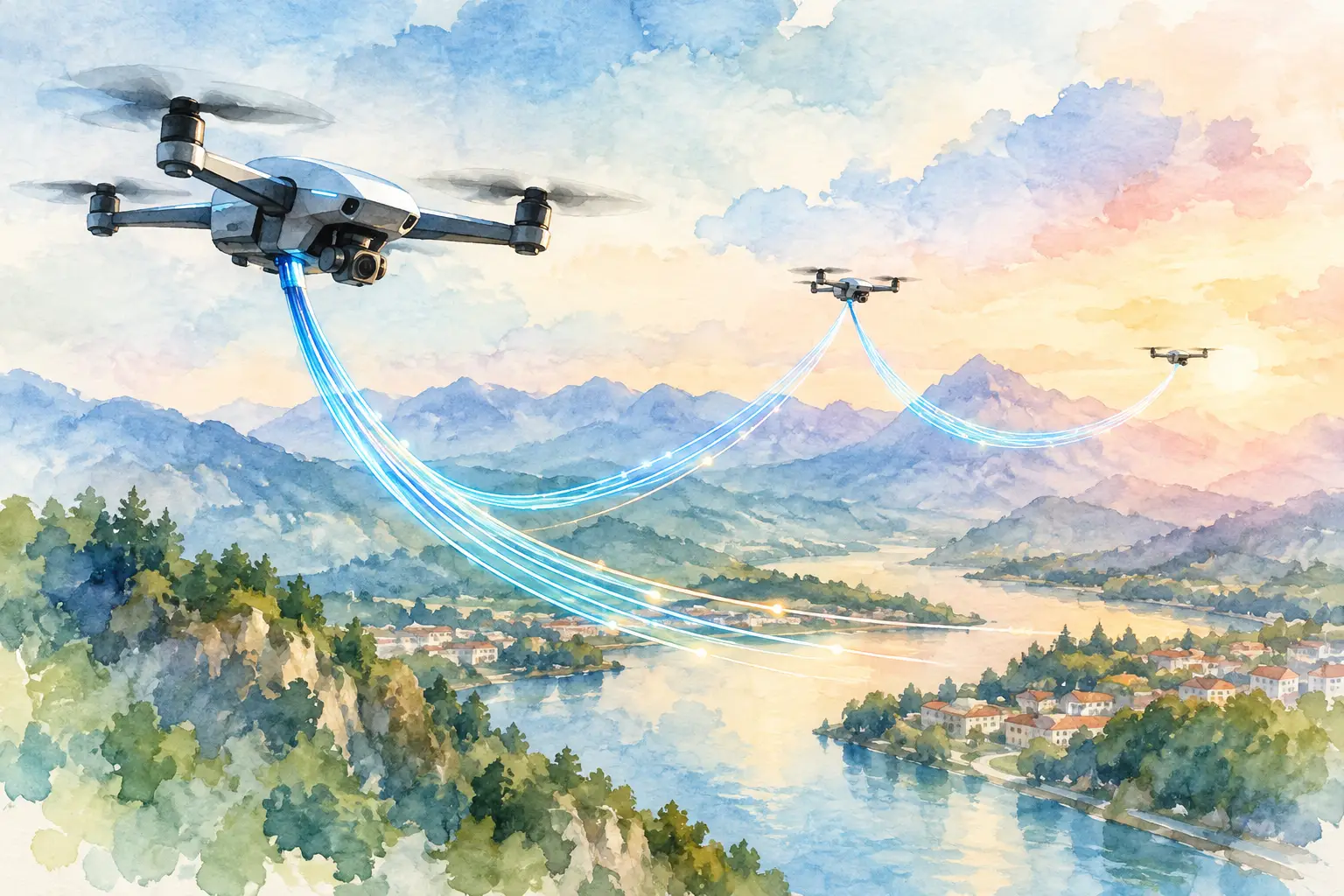
An optical-fibre-equipped drone carries a fibre optic line that pays out during flight from a spool or fibre optic disc. The line connects the aircraft to a ground-side control and display system. Control data travels towards the drone, while video telemetry or other data returns through the same physical link, depending on the equipment architecture.
Unlike a conventional 5.8 GHz FPV system, the core connection is not propagating through open air. Fibre carries information as light through a glass or polymer strand. This makes the link resistant to the RF interference, spectrum congestion and electromagnetic effects that can degrade radio-based command or video transmission.
For an FPV operator, the practical result is straightforward: image quality and control response are governed primarily by the optical hardware, system integration and condition of the deployed fibre, rather than antenna placement and RF noise alone. That does not make the aircraft immune to failure. It simply moves the critical risks from the radio environment to the mechanical and optical path.
Where fibre-equipped FPV builds make sense
The right use case starts with the mission profile. Optical fibre systems are most relevant where predictable link integrity matters more than untethered range, rapid relocation or minimum airframe weight. They can suit controlled inspections, specialist testing, protected sites and operations in dense electromagnetic environments, subject to local aviation, safety and site rules.
They are also relevant to builders developing purpose-specific aircraft rather than chasing a single all-round setup. A conventional FPV quad can be optimised around antenna gain, VTX output, receiver protocol and clean power. A fibre build needs to account for spool position, payout behaviour, airframe balance and the route the tether takes before and after launch.
That distinction matters. An optical setup should be treated as an integrated system, not as a fibre disc added to a standard build at the final stage.
The primary advantages
The clearest benefit is resistance to RF disruption. A fibre link does not depend on maintaining a usable radio channel between aircraft and pilot, so common RF constraints such as crowded spectrum, antenna masking and competing transmitters have far less influence over the primary path.
Video can also remain consistent where a traditional analogue or digital FPV feed would suffer breakup, delay or loss of usable image. For pilots who need dependable visual feedback for close, controlled flying, that consistency can be more valuable than headline transmission distance.
Fibre systems can also reduce the aircraft’s RF signature for the command-and-video connection. The operating environment and all applicable regulations still matter, and other onboard electronics may emit RF energy. The point is that the main control and video data path is no longer an over-the-air broadcast.
The trade-offs are physical, not theoretical
Every metre of fibre must go somewhere. The disc, spool or onboard dispenser adds mass, changes the centre of gravity and affects how the aircraft responds to acceleration. Fibre payout creates a mechanical interaction between the drone and the ground point, particularly during sharp turns, low-level flight or operations near obstacles.
Tether management is therefore central to performance. A snag, pinch, damaged section or poorly controlled payout can degrade the system faster than any minor tuning issue. Fibre is strong for its diameter, but it is not indestructible. Tight bends, abrasion, crush loads and contamination at connectors all deserve attention before launch.
Range is also more nuanced than it appears. A larger fibre disc may support a longer route, but it increases take-off weight and can reduce agility or endurance. A smaller disc keeps the aircraft lighter but limits operating distance. The right choice depends on the airframe’s thrust margin, battery capacity, expected flight path and safety reserve, not on fibre length in isolation.
Building around the optical link
A reliable fibre configuration begins with mechanical planning. Position the disc or spool so the aircraft remains balanced as fibre pays out. The centre of gravity can shift through the flight, especially where a significant amount of line is carried at launch. Confirm that the frame, fasteners and mounting system can withstand vibration without allowing the fibre unit to move.
Keep the payout path clean. Fibre should leave the disc without rubbing against propeller guards, arms, landing gear, carbon edges or exposed screws. A smooth exit angle reduces drag on the line and lowers the chance of damage during launch. If the build uses guides or protective sleeves, they should prevent abrasion without creating a point where the line can bind.
Power design matters too. The optical communication hardware, camera, flight controller and propulsion system must share a power plan that remains stable under throttle changes. Noise or voltage sag that would be tolerable in a basic bench test can become a serious problem once the aircraft is carrying a fibre disc and working under load. Use appropriately rated power distribution, verify regulator output and test the complete electronics stack before fitting propellers.
Match the link to the airframe
A compact platform may benefit from a lightweight fibre solution with a limited line length and a conservative flight profile. Larger custom frames can carry more fibre, but higher capacity does not excuse poor balance or insufficient thrust. Calculate the all-up weight with the full disc installed, then assess motor and propeller selection against the flight time and manoeuvrability you actually need.
The camera and display chain deserve the same attention. Optical fibre drone communication can preserve a clean transport path, but it cannot correct a poorly configured camera, incorrect video format or weak ground-side display. Validate resolution, frame rate, latency and control response as one system. If the operator cannot interpret the image quickly, link reliability alone will not deliver a better result.
Pre-flight checks that protect the link
A fibre-equipped drone needs a more disciplined pre-flight routine than an ordinary FPV quad. Inspect the fibre disc housing, payout route and any exposed lead-in section for kinks, abrasion or crushed areas. Check connectors for dust, damage and secure engagement. Then power the system and confirm video, command response and telemetry before the aircraft leaves the ground.
It is worth conducting initial tests at short distance in a clear, controlled area. Watch how the fibre releases during lift-off, gentle forward movement, turns and descent. Do not judge the setup only by a stationary bench test. The real question is whether the line pays out cleanly while the aircraft changes attitude and the pilot makes normal control inputs.
Operators should also plan the ground station position carefully. The launch point needs a clear path for the fibre and a stable working area for the control equipment. Avoid locations where the line could run across sharp edges, moving vehicles, pedestrian routes or machinery. Maintain situational awareness throughout the operation, and comply with the relevant CAA rules, landowner requirements and site procedures.
Choosing components for a dependable configuration
The lowest-priced disc is rarely the best value if it creates inconsistent payout, unnecessary weight or difficult integration. Choose fibre hardware based on the aircraft class, intended line length, connector compatibility, required data performance and mounting method. Confirm that the ground-side and air-side components are designed to work together rather than assuming similar connectors indicate full compatibility.
For custom builds, component-level sourcing gives you room to match the fibre disc, video hardware and airframe layout to the job. Aviadiag supports specialised FPV hardware requirements with optical fibre discs and direct sales contact for configurations that do not fit a standard product path.
The strongest fibre build is the one that respects its constraints. Start with a defined operating distance, payload target and flight profile, then select the airframe and optical components around those requirements. A carefully balanced, well-tested system will give you a far more useful result than simply fitting the longest fibre disc your frame can lift.