
Have Additional Questions? Contact Us: info(at)aviadiag.com

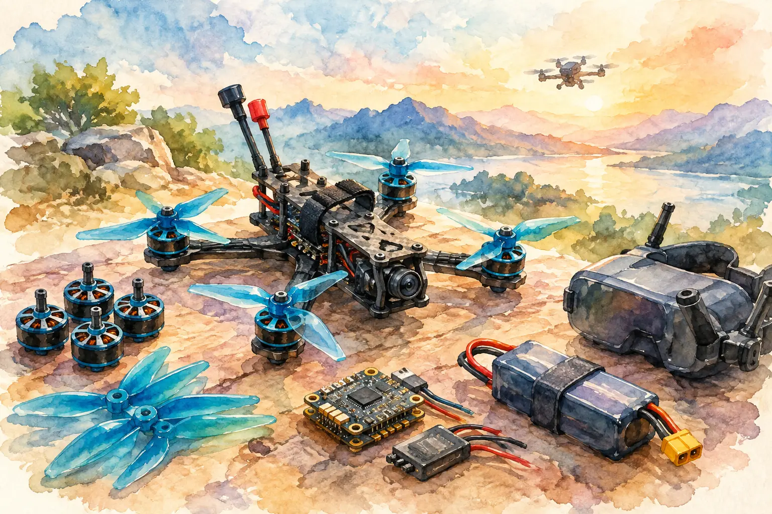
A reliable aircraft is rarely the result of one headline component. It comes from FPV drone parts that are selected as a working system: video link, power layout, mounting space, antenna placement and the conditions you expect to fly in. Whether you are replacing a failed unit or configuring a specialised airframe from the ground up, every component should serve a defined flight objective.
Start With the Flight Requirement
Before choosing hardware, define what the aircraft must do. A compact build flown around close obstacles has different priorities from a platform that needs consistent video across open terrain. Range, latency, interference, payload allowance, flight time and serviceability all affect the correct component choice.
This is where many builds lose performance. A high-output video transmitter may sound like the obvious upgrade, but it can add heat, draw more current and demand better antenna separation. An optical-fibre configuration may protect a critical link from radio-frequency congestion, yet it introduces its own routing, handling and integration requirements. There is no universal best part – there is a part that fits the mission, airframe and operating environment.
Keep the build objective specific. For example: maintain a clear live feed in a high-interference area; replace a damaged video-link component without changing the rest of the system; or create a tailored platform with specialised connectivity hardware. Once the objective is clear, component decisions become faster and more defensible.
FPV Drone Parts That Shape Link Performance
The video link deserves early attention because it affects both the pilot experience and operational awareness. The transmitter, receiver, antennas, power supply and installation geometry all contribute to what you see in goggles or on a monitor.
Video transmitters
An FPV video transmitter, often called a VTX, sends the camera feed from the aircraft to the ground-side receiver. Select it around the video format you need, available channels, output power, voltage input range, cooling provision and connector compatibility. A transmitter that fits electrically but cannot shed heat effectively may reduce performance or fail under sustained operation.
Mounting matters as much as the specification sheet. Keep the VTX away from sources of electrical noise where practical, secure it against vibration and avoid enclosing it in a way that traps heat. Confirm that the antenna connector is protected from impact and that the transmitter is never powered without a suitable antenna connected, unless the manufacturer explicitly permits it.
Higher power is not automatically better. It may improve margin in certain conditions, but it can create additional heat, consume more energy and require compliance with local radio rules. Choose output power for the actual route, environment and legal operating requirements, not simply for the largest number on the label.
Receivers and ground-side configuration
The receiver determines how effectively the ground station captures and presents the incoming signal. Compatibility with the transmitter’s video system comes first. Beyond that, consider receiver sensitivity, channel management, power arrangement, display integration and how easily the unit can be configured in the field.
A strong transmitter cannot compensate for a poorly positioned receiving antenna. Keep receiving antennas clear of obstructions, orient them for the flight area and avoid standing immediately behind materials that attenuate the signal. Test the complete airborne and ground-side system together. Bench checks identify wiring mistakes, but controlled field testing reveals multipath reflections, interference and blind spots that a workbench cannot show.
Antennas and the installation details that matter
Antennas are often treated as small accessories. They are critical RF components. Match the antenna frequency range and polarisation to the video system, protect the connector from strain and place the antenna where the frame, battery and other electronics will not unnecessarily shadow it.
For diversity or multi-antenna receiving arrangements, use antenna types that suit the expected flight profile. A broad-coverage antenna can support nearby manoeuvring, while a more directional option may favour a known flight corridor. The right arrangement depends on where the aircraft will be relative to the pilot, not on a fixed rule.
When Optical Fibre Is the Better Answer
Radio-frequency video systems remain practical for many FPV applications, but they are not the only option. FOP optical fibre discs support specialised configurations where a physical fibre link is required. This approach can suit operators working around demanding electromagnetic conditions or applications where link architecture must be designed around a defined route and platform.
Fibre is not a simple substitute for a radio link. It changes the build. Plan disc capacity, payout behaviour, fibre protection, routing path, mounting position and the effect on aircraft mass and balance. Poor routing can create snagging, abrasion or tension problems; poor placement can shift the centre of gravity or interfere with moving parts.
Treat optical fibre as a complete subsystem rather than an add-on. Inspect it before deployment, keep it clear of sharp edges and moving mechanisms, and establish a recovery plan for the operating area. The benefit comes from deliberate integration, not from fitting a disc after the rest of the aircraft has already been finalised.
Build for Electrical Stability and Fast Repairs
A clean signal starts with clean power. Video equipment is sensitive to voltage fluctuations and electrical noise, particularly on high-performance builds where motors, ESCs and digital systems are sharing a compact power layout. Confirm voltage compatibility at every connection and use suitable regulation and filtering where the design calls for it.
Do not assume a connector means two components are electrically compatible. Check pinout, voltage, polarity, current demand, signal format and control protocol before applying power. Label leads during assembly, provide strain relief and leave sensible access to connectors that may need servicing later.
Serviceability is a performance feature. Components buried beneath fixed plates, tightly stretched wiring or inaccessible fasteners make a simple repair slow and risky. A build designed for maintenance has clearly routed leads, protected connection points and enough room to inspect the VTX, receiver, camera and fibre hardware without dismantling half the airframe.
It also helps to keep known-good spares for the components most likely to halt an operation: antennas, connecting leads, compatible power adapters and key video-link hardware. The aim is not to carry every possible part. It is to eliminate the single failures that leave an otherwise capable aircraft grounded.
Match Components Before You Commit
The quickest way to prevent an expensive mismatch is to validate the whole chain before final installation. Start at the camera or video source, then follow the signal through the transmitter, antenna, receiving equipment and display. In parallel, trace the power route from battery to regulator and each connected device.
Check physical constraints as carefully as electrical ones. Measure mounting patterns, connector clearance, antenna exit direction, cooling space and the position of the battery at the expected centre of gravity. A component that technically fits can still compromise access, airflow or balance.
For non-standard requirements, direct component-level sourcing is more useful than trying to force a consumer ready-to-fly layout into a specialised role. Aviadiag provides FPV transmitters, receivers, FOP optical fibre discs and specialised hardware for builders who need their system to fit a clear operational vision rather than a generic specification.
Test the System in Stages
Power the aircraft for the first time without propellers fitted. Verify supply voltage, video output, receiver response, antenna connections and component temperatures. Confirm the image remains stable while the motors are armed only when it is safe and appropriate to do so, because electrical noise may not appear at idle.
Then move to a controlled outdoor test area and assess the real link. Watch for image breakup, heat build-up, changing performance with aircraft orientation and any effect created by the pilot’s position or nearby structures. Change one variable at a time. Replacing the transmitter, receiver and antenna arrangement all at once makes it difficult to identify what improved the result – or what introduced the fault.
Operate within applicable aviation, spectrum and site rules, and never treat link testing as a substitute for safe flight planning. A dependable video system supports good decisions, but it does not remove the need for line-of-sight awareness, airspace discipline and a suitable recovery plan.
The right component set makes an aircraft easier to fly, easier to repair and more capable of meeting its intended role. Build around the signal path and operating requirement first, then select FPV hardware that earns its place on the frame.