Have Additional Questions? Contact Us: info(at)aviadiag.com


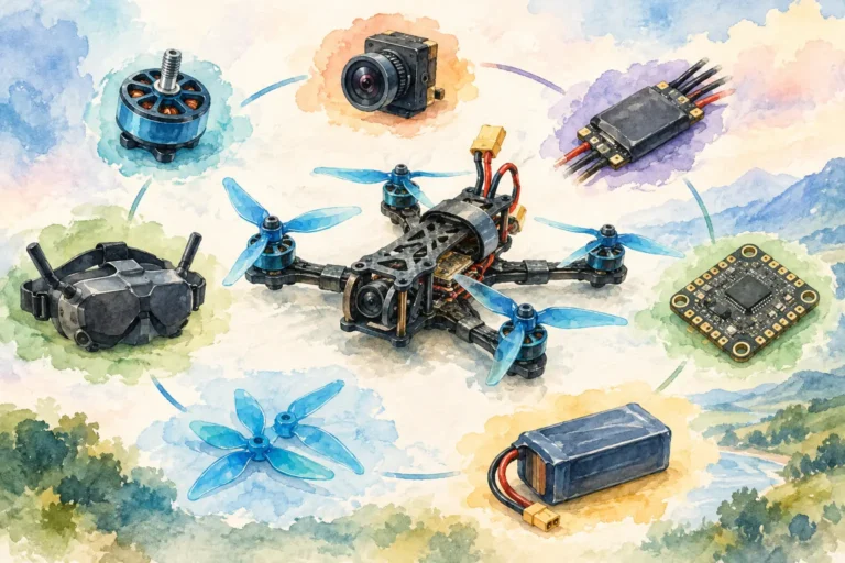
A clean bench image can turn into rolling lines, flicker or snow the moment the motors arm. To diagnose FPV image noise properly, treat the video system as a chain: camera, power supply, flight controller, VTX, antenna, receiver and goggles. Change one part of that chain at a time. Guessing at the fault usually leads to unnecessary replacements and a heavier, less reliable build.
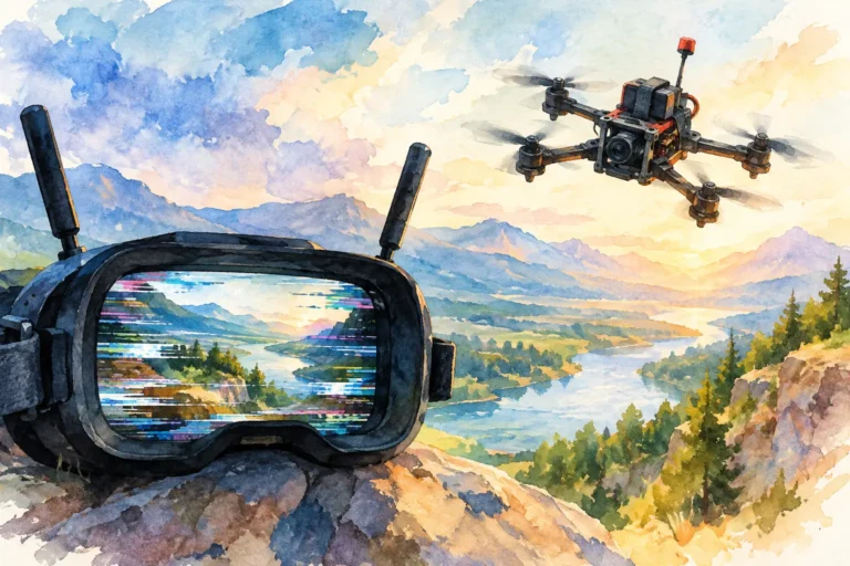
The pattern of the interference matters. Noise that follows throttle points towards electrical power or motor-related interference. A picture that breaks up only with distance is usually an RF link issue. A permanently soft, grainy or unstable image can originate at the camera, VTX, receiver or antenna connection. Start by identifying when the fault appears, then test under controlled conditions before changing hardware.
Diagnose FPV Image Noise by Its Behaviour
The fastest diagnosis begins before the soldering iron comes out. Put the quad on the bench with props removed, use the same goggles and receiver you fly with, and observe the image at each stage: powered but disarmed, armed at idle, and during a short motor run. If possible, test with a known-good battery as well. A tired or damaged pack can create voltage behaviour that looks like a component fault.
Horizontal lines that sweep or pulse as throttle rises are the familiar signature of electrical noise entering the camera or VTX supply. It can be caused by noisy ESC switching, inadequate filtering, poor grounding, a failing regulator or power leads routed too close to high-current wiring. The key clue is correlation. If the lines change frequency with motor speed, look at the power path before blaming the antenna.
A sudden loss of clarity, static or image breakup that worsens as the aircraft moves away is different. That is normally an RF problem: incorrect channel matching, low VTX output power, a damaged antenna, polarisation mismatch, obstructed antenna placement or a receiver limitation. If the video remains clear on the bench but fails at range, power filtering is less likely to be the primary cause.
Noise that appears randomly after a crash deserves a close mechanical inspection. A loose MMCX or u.FL connector, partly broken antenna coax, cracked solder joint or camera plug under tension can create intermittent video faults that are hard to reproduce. Flex the suspect wiring gently with the system powered, without allowing conductors to short, and watch for image changes.
Start With a Clean, Known-Good Video Test
Separate the aircraft from the environment. Nearby Wi-Fi equipment, other pilots, high-power transmitters and even a poorly selected channel can complicate testing. Confirm that the VTX and receiver are on the same channel and band, not merely a similarly numbered frequency. Check the VTX power setting too. Many units boot at a low-power or pit-mode setting until they are armed or specifically configured.
Then inspect the antenna system. A circularly polarised VTX antenna should be matched to a receiver antenna with the same polarisation. Right-hand and left-hand circular polarisation do not mix well. A linear antenna can work, but it sacrifices some rejection of reflected signal and often performs less predictably around structures.
Never power a VTX without an antenna attached. The immediate concern is not image noise but potential damage to the transmitter output stage. Also inspect the antenna connector itself. A connector that feels secure can still have a lifted centre pin, strained coax or damaged shield. For range-related noise, swapping in a known-good antenna pair is one of the most decisive tests available.
Receiver setup matters as much as airborne hardware. Check that diversity antennas are positioned for their intended role, and that the goggles or ground receiver are not being shielded by your body, vehicle or nearby conductive surfaces. For demanding locations, a directional antenna paired with an omni antenna can improve usable coverage, but only when aimed and configured correctly. More gain is not a universal fix – a directional antenna has a narrower coverage area and requires disciplined positioning.
Trace Throttle-Related Noise Through the Power System
When interference rises with throttle, begin at the camera and VTX power inputs. Review where each component receives voltage. A camera powered from a noisy rail may send interference straight into the image before the VTX ever sees it. Likewise, a VTX supplied from a weak or overloaded regulator can produce lines, flicker or resets during punch-outs.
Use the regulated supply voltage specified for each component. Sending battery voltage to hardware that expects a regulated 5 V or 9 V feed risks more than poor image quality. At the same time, do not assume a labelled 5 V pad is automatically clean enough for video equipment. On a hard-driven build, regulator noise and ground contamination can still reach sensitive video circuits.
A practical isolation test is to power the camera or VTX from a separate suitable regulated source while keeping the video signal connected. If the image becomes clean, the original supply path is the problem. If it remains unchanged, inspect the signal wiring and the component itself. Make this test methodically. Changing the power source, camera and antenna at once may improve the image, but it tells you nothing about which fault was present.
Ground routing is often overlooked. Camera ground, VTX ground and the flight controller reference need a sound common return path. Long, thin ground wires or poorly made solder joints increase resistance and make the system more vulnerable to voltage variation. Keep camera and video wiring away from battery leads, ESC motor wires and high-current solder pads where practical. Crossing is usually better than running parallel for a long distance.
A low-ESR capacitor across the main battery input can reduce high-frequency voltage spikes from ESC switching. It is not a cure for every noisy build. A capacitor will not repair a damaged camera, poor antenna polarisation or a VTX operating on the wrong channel. But on a throttle-sensitive analogue system, correctly fitted input filtering is often a high-value improvement. Choose voltage and capacitance ratings suitable for the battery system, and keep the capacitor leads short.
Check the Camera, Video Wiring and VTX
If the image is noisy even with motors stopped, test the camera first. Connect it to a known-good VTX and power source, or substitute a known-good camera into the existing build. Camera faults can appear as fixed grain, colour shifts, flicker in changing light or complete sync instability. Check the camera settings as well. Exposure, WDR and low-light modes can make normal sensor behaviour look like transmission noise, particularly indoors under LED lighting.
Next, inspect the video signal conductor. A pinched wire, oxidised connector or cold solder joint may pass an image while adding instability. Video wiring should be short, secure and protected from vibration. If your flight controller provides an OSD path, bypass it temporarily where the configuration allows. A clean direct camera-to-VTX test can identify whether the flight controller video path or its wiring is introducing the fault.
VTX heat is another variable. Some transmitters reduce output power or behave inconsistently when airflow is poor, especially during extended bench testing. Allow the VTX adequate cooling and avoid judging thermal behaviour after several minutes sitting still at high output power. A fault that occurs only after a flight may be temperature-related, but it may also be a battery-voltage or vibration issue. Repeat the test rather than assuming.
Use a Controlled Swap Order
Avoid replacing parts at random. A disciplined order preserves time and budget: confirm channel and antenna condition, test a clean power source, inspect wiring and grounds, substitute the camera, then substitute the VTX or receiver. Keep one known-good antenna and one known-good camera available for fault finding. They are more useful than a box of untested spares.
For custom airframes and specialised video-link requirements, component compatibility should be considered as a system. VTX voltage tolerance, antenna connector type, camera output format, flight controller layout and the intended operating environment all affect the result. Aviadiag supplies specialised FPV transmitters, receivers and connectivity hardware for builders who need to configure beyond standard setups, but the strongest upgrade is still the one that addresses the verified fault.
When the Image Is Clean on the Bench but Not in Flight
A bench test cannot reproduce prop wash, vibration, current draw, changing orientation and distance. If noise appears only airborne, review your blackbox data or flight observations alongside the video. Does it begin during hard throttle, in a certain direction, after several minutes, or near a particular location? Those details narrow the search far more effectively than the general description of a “bad signal”.
Also account for installation changes made after the last clean flight. A new action camera mount can obstruct an antenna. A GPS unit or receiver relocation can alter cable routing. A replacement frame plate may pinch a coax lead. On compact builds, even a few millimetres of antenna position can change exposure to carbon fibre, electronics and the pilot’s body.
A dependable FPV feed is built through evidence, not luck. Record the symptom, isolate one variable, and test again under the same conditions. That process turns image noise from an unpredictable annoyance into a solvable system fault, leaving you with a video link ready for the flight you actually intend to make.