Have Additional Questions? Contact Us: info(at)aviadiag.com

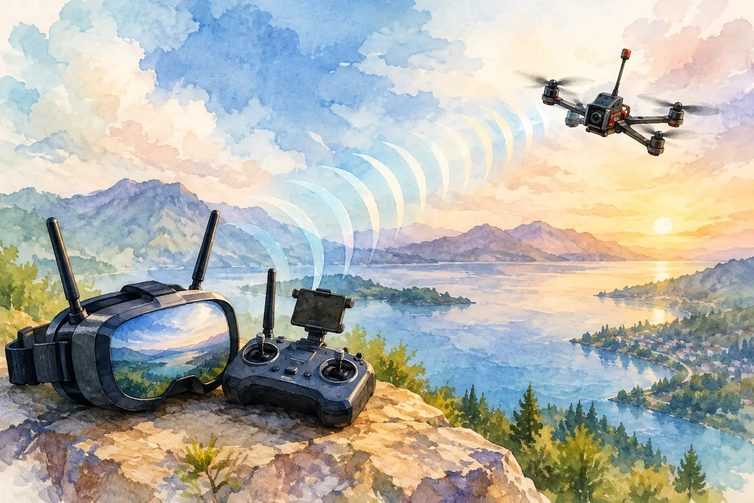
A video feed that looks perfect on the bench can fail quickly once the aircraft turns behind a tree line, drops below a ridge, or flies into a noisy operating area. This video link budgeting guide gives FPV builders a practical way to predict that margin before committing hardware to a build. The aim is not to chase the highest transmitter power on the specification sheet. It is to build a link that maintains usable video through the range, terrain and manoeuvres your aircraft is expected to handle.
What a video link budget tells you
A link budget is an accounting exercise measured in decibels (dB). Start with the signal leaving the video transmitter, then subtract every predictable loss between the aircraft and ground station. Compare the remaining signal at the receiver with the receiver sensitivity required for your selected video mode.
The result is your link margin. A positive margin means the receiver should have enough signal under the assumptions used. A slim margin may work in open air but leave little tolerance for antenna orientation, interference, weather, airframe masking or imperfect installation. A healthy margin gives the system room to keep delivering useful video when conditions stop being ideal.
For digital FPV, receiver sensitivity is tied to the selected bitrate, bandwidth and modulation mode. A low-latency, high-throughput mode often needs a stronger signal than a lower-rate or more resilient mode. Analogue systems work differently, but the same principle applies: the picture degrades as received signal falls, and the acceptable threshold depends on how much noise and image loss the operator can tolerate.
The core FPV video link budget formula
Use this simplified calculation:
Received power (dBm) = transmitter power (dBm) + transmitter antenna gain (dBi) + receiver antenna gain (dBi) – free-space path loss (dB) – cable and connector losses (dB) – additional losses (dB)
Then calculate:
Link margin (dB) = received power (dBm) – receiver sensitivity (dBm)
The units matter. Transmitter power is often quoted in milliwatts, while a link budget uses dBm. Common reference points are 25 mW = 14 dBm, 100 mW = 20 dBm, 400 mW = 26 dBm, 1 W = 30 dBm and 2 W = 33 dBm. Each 3 dB increase approximately doubles power, while a 10 dB increase represents roughly ten times the power.
That relationship explains why power alone is rarely the most efficient upgrade. Moving from 1 W to 2 W gains only 3 dB. Improving a poorly positioned ground antenna, removing a lossy adaptor, or choosing a receiver with better sensitivity can deliver a similar or greater real-world improvement without increasing airborne heat and electrical demand.
Free-space path loss sets the baseline
Free-space path loss is the signal reduction caused by distance alone. For kilometres and MHz, use:
FSPL (dB) = 32.44 + 20 log10(distance in km) + 20 log10(frequency in MHz)
At 5.8 GHz over 1 km, free-space path loss is about 108 dB. At 2 km, it rises by 6 dB, not 3 dB. Every doubling of distance costs approximately 6 dB. This is why a system that seems comfortable at 1 km can become marginal much sooner than expected.
Free-space calculations are optimistic by design. They assume a clear, unobstructed path. Trees, buildings, terrain, the pilot’s body, wet foliage and the aircraft frame introduce further loss. Treat the calculation as a starting point, not a guarantee of field range.
Build the budget from real component data
Start with the actual output power your VTX can sustain, not its highest selectable number. A transmitter may reduce output when it overheats, receive lower voltage than expected, or be configured for a different regional power setting. Confirm the output mode, supply voltage, cooling arrangement and channel before flight testing.
Next, record antenna gain and polarisation. A circularly polarised antenna pair helps reject multipath reflections when both ends use the same handedness. Mixing left-hand and right-hand circular polarisation can impose a major penalty. Linear antennas can perform well in a matched system, but aircraft roll and pitch alter alignment. That can make them less forgiving in dynamic FPV flight.
Cable loss deserves more attention than it receives. A short, quality RF lead has a small but measurable effect. Long thin coax, poor crimps, damaged connectors and stacked adaptors consume margin that was expensive to create at the transmitter. On a high-frequency video system, keep RF runs short, use appropriate cable, and avoid adding connectors merely for convenience.
Receiver sensitivity should come from a credible specification for the mode you intend to use. Do not compare sensitivity figures between products unless bandwidth, bitrate and test conditions are equivalent. A claimed sensitivity number without operating context is not enough to build a useful budget.
Allow margin for the flight you actually plan
A 0 dB result is not a target. It means the expected received signal only just meets the receiver threshold in the model. There is no reserve for real conditions.
For clear line-of-sight flights with carefully installed antennas, a 10 dB margin may be workable. For complex terrain, low-level flight, urban RF congestion or missions where video continuity is operationally significant, plan more reserve. A 15 to 20 dB target is often a more practical design position, although the required margin depends on the consequences of a degraded feed and the recovery options available.
Do not confuse margin with permission to fly beyond visual line of sight or outside applicable radio and aviation rules. Use the budget to improve system reliability within your authorised operating conditions, local spectrum requirements and safe flight plan.
Account for airframe masking and orientation
The drone itself can become part of the RF problem. Carbon fibre, batteries, electronics and payloads can block or distort antenna patterns. A VTX antenna tucked behind a battery may show a strong signal in one heading and a sudden weak sector when the aircraft turns.
Mount the antenna where it has clear exposure away from conductive structure and high-current wiring. Secure it so prop wash and manoeuvres do not change its position. At the ground station, place receiving antennas above the ground where possible and keep directional antennas aimed at the intended operating area. A diversity receiver combining an omnidirectional antenna with a directional antenna can reduce orientation-related dropouts, but only if both antennas are selected and placed with purpose.
Worked example: a 5.8 GHz FPV link
Assume an aircraft uses a 1 W VTX, equivalent to 30 dBm. The aircraft has a 1 dBi circularly polarised antenna. The ground station uses a 9 dBi directional antenna. At 2 km on 5.8 GHz, free-space path loss is roughly 114 dB.
Before extra losses, the calculation is 30 + 1 + 9 – 114 = -74 dBm. Allow 2 dB for cable, connectors and installation effects, leaving -76 dBm at the receiver. If the selected digital mode has a receiver sensitivity of -90 dBm, the theoretical margin is 14 dB.
That is a reasonable starting point for clean line of sight, but it is not a promise of 2 km through trees or behind terrain. If the aircraft banks and the airframe masks the antenna, or if the ground antenna is not kept on target, the reserve can disappear. The better response may be improving antenna placement or ground-station gain rather than immediately fitting a higher-power transmitter.
Spend your budget where it changes performance
When a calculation comes up short, improve the system in the order that creates the least compromise. First remove preventable loss: inspect connectors, shorten RF paths and replace damaged antennas. Then improve antenna placement and pattern choice. A well-positioned receiver antenna can add useful gain without adding airborne mass, heat or current draw.
After that, consider receiver performance and video mode. Lowering bitrate or choosing a more resilient setting may improve sensitivity and give the link more room to work, though image quality can fall. Finally, assess transmitter power against thermal management, power supply capacity, local limits and the extra RF noise that a high-power installation can create for nearby systems.
For specialised builds, select the VTX, receiver and antenna system as one chain. Aviadiag supplies FPV video components for builders who need to match hardware to a defined range, installation and performance target rather than accept a standard configuration.
Validate the numbers in the field
A link budget is only useful when checked against controlled flight testing. Start at short range and verify that VTX temperature, supply voltage, video mode and receiver behaviour match the assumptions. Extend distance gradually in clear line of sight, then test representative headings, altitudes and manoeuvres while maintaining safe operating practice.
Record where video quality changes, not only where it fails. A repeatable weak sector often points to antenna masking or polarisation mismatch. A gradual decline at range may match the budget. Sudden interference can indicate channel conflict, receiver desensitisation or an installation problem that maths alone will not reveal.
Build for measured margin, not marketing range. When every dB has a purpose, the video system becomes a dependable part of the aircraft rather than the component that limits where your flight vision can go.